Software Requirements Specification for Solar Water Heating Systems Incorporating PCM

Thulasi Jegatheesan, Brooks MacLachlan, and W. Spencer Smith

Table of Contents

An outline of all sections included in this SRS is recorded here for easy reference.

Reference Material

This section records information for easy reference.

Table of Units

The unit system used throughout is SI (Système International d'Unités). In addition to the basic units, several derived units are also used. For each unit, the Table of Units lists the symbol, a description, and the SI name.

Symbol Description SI Name
°C temperature centigrade
J energy joule
kg mass kilogram
m length metre
s time second
W power watt

Table of Units

Table of Symbols

The symbols used in this document are summarized in the Table of Symbols along with their units. The choice of symbols was made to be consistent with the heat transfer literature and with existing documentation for solar water heating systems. The symbols are listed in alphabetical order. For vector quantities, the units shown are for each component of the vector.

Symbol Description Units
AC Heating coil surface area m2
ACmax Maximum surface area of coil m2
Ain Surface area over which heat is transferred in m2
Aout Surface area over which heat is transferred out m2
AP Phase change material surface area m2
AR Aspect ratio --
ARmax Maximum aspect ratio --
ARmin Minimum aspect ratio --
C Specific heat capacity \(\frac{\text{J}}{\text{kg}{}^{\circ}\text{C}}\)
CL Specific heat capacity of a liquid \(\frac{\text{J}}{\text{kg}{}^{\circ}\text{C}}\)
CS Specific heat capacity of a solid \(\frac{\text{J}}{\text{kg}{}^{\circ}\text{C}}\)
CV Specific heat capacity of a vapour \(\frac{\text{J}}{\text{kg}{}^{\circ}\text{C}}\)
CPL Specific heat capacity of PCM as a liquid \(\frac{\text{J}}{\text{kg}{}^{\circ}\text{C}}\)
CPS Specific heat capacity of PCM as a solid \(\frac{\text{J}}{\text{kg}{}^{\circ}\text{C}}\)
Ctol Relative tolerance for conservation of energy --
CW Specific heat capacity of water \(\frac{\text{J}}{\text{kg}{}^{\circ}\text{C}}\)
CWmax Maximum specific heat capacity of water \(\frac{\text{J}}{\text{kg}{}^{\circ}\text{C}}\)
CWmin Minimum specific heat capacity of water \(\frac{\text{J}}{\text{kg}{}^{\circ}\text{C}}\)
CPLmax Maximum specific heat capacity of PCM as a liquid \(\frac{\text{J}}{\text{kg}{}^{\circ}\text{C}}\)
CPLmin Minimum specific heat capacity of PCM as a liquid \(\frac{\text{J}}{\text{kg}{}^{\circ}\text{C}}\)
CPSmax Maximum specific heat capacity of PCM as a solid \(\frac{\text{J}}{\text{kg}{}^{\circ}\text{C}}\)
CPSmin Minimum specific heat capacity of PCM as a solid \(\frac{\text{J}}{\text{kg}{}^{\circ}\text{C}}\)
D Diameter of tank m
E Sensible heat J
EP Change in heat energy in the PCM J
EW Change in heat energy in the water J
EPmeltinit Change in heat energy in the PCM at the instant when melting begins J
g Volumetric heat generation per unit volume \(\frac{\text{W}}{\text{m}^{3}}\)
Hf Specific latent heat of fusion \(\frac{\text{J}}{\text{kg}}\)
Hfmax Maximum specific latent heat of fusion \(\frac{\text{J}}{\text{kg}{}^{\circ}\text{C}}\)
Hfmin Minimum specific latent heat of fusion \(\frac{\text{J}}{\text{kg}{}^{\circ}\text{C}}\)
h Convective heat transfer coefficient \(\frac{\text{W}}{\text{m}^{2}{}^{\circ}\text{C}}\)
hC Convective heat transfer coefficient between coil and water \(\frac{\text{W}}{\text{m}^{2}{}^{\circ}\text{C}}\)
hCmax Maximum convective heat transfer coefficient between coil and water \(\frac{\text{W}}{\text{m}^{2}{}^{\circ}\text{C}}\)
hCmin Minimum convective heat transfer coefficient between coil and water \(\frac{\text{W}}{\text{m}^{2}{}^{\circ}\text{C}}\)
hmin Minimum thickness of a sheet of PCM m
hP Convective heat transfer coefficient between PCM and water \(\frac{\text{W}}{\text{m}^{2}{}^{\circ}\text{C}}\)
hPmax Maximum convective heat transfer coefficient between PCM and water \(\frac{\text{W}}{\text{m}^{2}{}^{\circ}\text{C}}\)
hPmin Minimum convective heat transfer coefficient between PCM and water \(\frac{\text{W}}{\text{m}^{2}{}^{\circ}\text{C}}\)
L Length of tank m
Lmax Maximum length of tank m
Lmin Minimum length of tank m
m Mass kg
mP Mass of phase change material kg
mW Mass of water kg
MINFRACT Minimum fraction of the tank volume taken up by the PCM --
Unit outward normal vector for a surface --
Q Latent heat J
QP Latent heat energy added to PCM J
q Heat flux \(\frac{\text{W}}{\text{m}^{2}}\)
qC Heat flux into the water from the coil \(\frac{\text{W}}{\text{m}^{2}}\)
qin Heat flux input \(\frac{\text{W}}{\text{m}^{2}}\)
qout Heat flux output \(\frac{\text{W}}{\text{m}^{2}}\)
qP Heat flux into the PCM from water \(\frac{\text{W}}{\text{m}^{2}}\)
q Thermal flux vector \(\frac{\text{W}}{\text{m}^{2}}\)
S Surface m2
T Temperature °C
ΔT Change in temperature °C
Tboil Boiling point temperature °C
TC Temperature of the heating coil °C
Tenv Temperature of the environment °C
Tinit Initial temperature °C
Tmelt Melting point temperature °C
TmeltP Melting point temperature for PCM °C
TP Temperature of the phase change material °C
TW Temperature of the water °C
t Time s
tfinal Final time s
tfinalmax Maximum final time s
tmeltfinal Time at which melting of PCM ends s
tmeltinit Time at which melting of PCM begins s
tstep Time step for simulation s
V Volume m3
VP Volume of PCM m3
Vtank Volume of the cylindrical tank m3
VW Volume of water m3
η ODE parameter related to decay rate --
π Ratio of circumference to diameter for any circle --
ρ Density \(\frac{\text{kg}}{\text{m}^{3}}\)
ρP Density of PCM \(\frac{\text{kg}}{\text{m}^{3}}\)
ρPmax Maximum density of PCM \(\frac{\text{kg}}{\text{m}^{3}}\)
ρPmin Minimum density of PCM \(\frac{\text{kg}}{\text{m}^{3}}\)
ρW Density of water \(\frac{\text{kg}}{\text{m}^{3}}\)
ρWmax Maximum density of water \(\frac{\text{kg}}{\text{m}^{3}}\)
ρWmin Minimum density of water \(\frac{\text{kg}}{\text{m}^{3}}\)
τ Dummy variable for integration over time s
τPL ODE parameter for liquid PCM s
τPS ODE parameter for solid PCM s
τW ODE parameter for water related to decay time s
ϕ Melt fraction --
Gradient --

Table of Symbols

Abbreviations and Acronyms

Abbreviation Full Form
A Assumption
DD Data Definition
GD General Definition
GS Goal Statement
IM Instance Model
LC Likely Change
ODE Ordinary Differential Equation
PCM Phase Change Material
PS Physical System Description
R Requirement
RHS Right-Hand Side
RefBy Referenced by
Refname Reference Name
SRS Software Requirements Specification
SWHS Solar Water Heating System
TM Theoretical Model
UC Unlikely Change
Uncert. Typical Uncertainty

Abbreviations and Acronyms

Introduction

Due to increasing costs, diminishing availability, and negative environmental impact of fossil fuels, the demand is high for renewable energy sources and energy storage technology. Solar water heating systems incorporating phase change material (PCM) use a renewable energy source and provide a novel way of storing energy. Solar water heating systems incorporating PCM improve over the traditional solar water heating systems because of their smaller size. The smaller size is possible because of the ability of PCM to store thermal energy as latent heat, which allows higher thermal energy storage capacity per unit weight.

The following section provides an overview of the Software Requirements Specification (SRS) for solar water heating systems incorporating PCM. The developed program will be referred to as Solar Water Heating System (SWHS) based on the original, manually created version of SWHS. This section explains the purpose of this document, the scope of the requirements, the characteristics of the intended reader, and the organization of the document.

Purpose of Document

The primary purpose of this document is to record the requirements of SWHS. Goals, assumptions, theoretical models, definitions, and other model derivation information are specified, allowing the reader to fully understand and verify the purpose and scientific basis of SWHS. With the exception of system constraints, this SRS will remain abstract, describing what problem is being solved, but not how to solve it.

This document will be used as a starting point for subsequent development phases, including writing the design specification and the software verification and validation plan. The design document will show how the requirements are to be realized, including decisions on the numerical algorithms and programming environment. The verification and validation plan will show the steps that will be used to increase confidence in the software documentation and the implementation. Although the SRS fits in a series of documents that follow the so-called waterfall model, the actual development process is not constrained in any way. Even when the waterfall model is not followed, as Parnas and Clements point out parnasClements1986, the most logical way to present the documentation is still to "fake" a rational design process.

Scope of Requirements

The scope of the requirements includes thermal analysis of a single solar water heating tank incorporating PCM. This entire document is written assuming that the substances inside the solar water heating tank are water and PCM.

Characteristics of Intended Reader

Reviewers of this documentation should have an understanding of heat transfer theory from level 3 or 4 mechanical engineering and differential equations from level 1 and 2 calculus. The users of SWHS can have a lower level of expertise, as explained in Sec:User Characteristics.

Organization of Document

The organization of this document follows the template for an SRS for scientific computing software proposed by koothoor2013, smithLai2005, smithEtAl2007, and smithKoothoor2016. The presentation follows the standard pattern of presenting goals, theories, definitions, and assumptions. For readers that would like a more bottom up approach, they can start reading the instance models and trace back to find any additional information they require.

The goal statements are refined to the theoretical models and the theoretical models to the instance models. The instance models to be solved are referred to as IM:eBalanceOnWtr, IM:eBalanceOnPCM, IM:heatEInWtr, and IM:heatEInPCM. The instance models provide the ordinary differential equations (ODEs) and algebraic equations that model the solar water heating systems incorporating PCM. SWHS solves these ODEs.

General System Description

This section provides general information about the system. It identifies the interfaces between the system and its environment, describes the user characteristics, and lists the system constraints.

System Context

Fig:SysCon shows the system context. A circle represents an external entity outside the software, the user in this case. A rectangle represents the software system itself (SWHS). Arrows are used to show the data flow between the system and its environment.

<a href=#Figure:SysCon>Fig:SysCon</a>: System Context
Figure: Fig:SysCon: System Context

SWHS is mostly self-contained. The only external interaction is through the user interface. The responsibilities of the user and the system are as follows:

  • User Responsibilities:
    • Provide the input data to the system, ensuring no errors in the data entry
    • Take care that consistent units are used for input variables
  • SWHS Responsibilities:
    • Detect data type mismatch, such as a string of characters instead of a floating point number
    • Determine if the inputs satisfy the required physical and software constraints
    • Calculate the required outputs

User Characteristics

The end user of SWHS should have an understanding of undergraduate Level 1 Calculus and Physics.

System Constraints

There are no system constraints.

Specific System Description

This section first presents the problem description, which gives a high-level view of the problem to be solved. This is followed by the solution characteristics specification, which presents the assumptions, theories, and definitions that are used.

Problem Description

A system is needed to investigate the effect of employing PCM within a solar water heating tank.

Terminology and Definitions

This subsection provides a list of terms that are used in the subsequent sections and their meaning, with the purpose of reducing ambiguity and making it easier to correctly understand the requirements.

  • Heat flux: The rate of thermal energy transfer through a given surface per unit time.
  • Phase change material: A substance that uses phase changes (such as melting) to absorb or release large amounts of heat at a constant temperature.
  • Specific heat capacity: The amount of energy required to raise the temperature of the unit mass of a given substance by a given amount.
  • Thermal conduction: The transfer of heat energy through a substance.
  • Transient: Changing with time.

Physical System Description

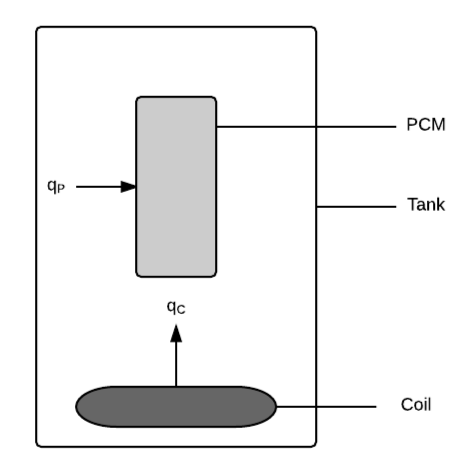
The physical system of SWHS, as shown in Fig:Tank, includes the following elements:

PS1: Tank containing water.

PS2: Heating coil at bottom of tank. (qC represents the heat flux into the water from the coil.)

PS3: PCM suspended in tank. (qP represents the heat flux into the PCM from water.)

Solar water heating tank, with heat flux into the water from the coil of <em>q<sub>C</sub></em> and heat flux into the PCM from water of <em>q<sub>P</sub></em>
Figure: Solar water heating tank, with heat flux into the water from the coil of qC and heat flux into the PCM from water of qP

Goal Statements

Given the temperature of the heating coil, the initial conditions for the temperature of the water and the temperature of the phase change material, and the material properties, the goal statements are:

Predict-Water-Temperature: Predict the temperature of the water over time.

Predict-PCM-Temperature: Predict the temperature of the phase change material over time.

Predict-Water-Energy: Predict the change in heat energy in the water over time.

Predict-PCM-Energy: Predict the change in heat energy in the PCM over time.

Solution Characteristics Specification

The instance models that govern SWHS are presented in the Instance Model Section. The information to understand the meaning of the instance models and their derivation is also presented, so that the instance models can be verified.

Assumptions

This section simplifies the original problem and helps in developing the theoretical models by filling in the missing information for the physical system. The assumptions refine the scope by providing more detail.

Thermal-Energy-Only: The only form of energy that is relevant for this problem is thermal energy. All other forms of energy, such as mechanical energy, are assumed to be negligible. (RefBy: TM:consThermE.)

Heat-Transfer-Coeffs-Constant: All heat transfer coefficients are constant over time. (RefBy: TM:nwtnCooling.)

Constant-Water-Temp-Across-Tank: The water in the tank is fully mixed, so the temperature of the water is the same throughout the entire tank. (RefBy: GD:rocTempSimp, IM:eBalanceOnWtr, and IM:eBalanceOnPCM.)

Temp-PCM-Constant-Across-Volume: The temperature of the phase change material is the same throughout the volume of PCM. (RefBy: GD:rocTempSimp, IM:eBalanceOnWtr, IM:eBalanceOnPCM, and LC:Uniform-Temperature-PCM.)

Density-Water-PCM-Constant-over-Volume: The density of water and density of PCM have no spatial variation; that is, they are each constant over their entire volume. (RefBy: GD:rocTempSimp.)

Specific-Heat-Energy-Constant-over-Volume: The specific heat capacity of water, specific heat capacity of PCM as a solid, and specific heat capacity of PCM as a liquid have no spatial variation; that is, they are each constant over their entire volume. (RefBy: GD:rocTempSimp.)

Newton-Law-Convective-Cooling-Coil-Water: Newton's law of convective cooling applies between the heating coil and the water. (RefBy: GD:htFluxWaterFromCoil.)

Temp-Heating-Coil-Constant-over-Time: The temperature of the heating coil is constant over time. (RefBy: GD:htFluxWaterFromCoil and LC:Temperature-Coil-Variable-Over-Day.)

Temp-Heating-Coil-Constant-over-Length: The temperature of the heating coil does not vary along its length. (RefBy: IM:eBalanceOnWtr and LC:Temperature-Coil-Variable-Over-Length.)

Law-Convective-Cooling-Water-PCM: Newton's law of convective cooling applies between the water and the PCM. (RefBy: GD:htFluxPCMFromWater.)

Charging-Tank-No-Temp-Discharge: The model only accounts for charging of the tank, not discharging. The temperature of the water and temperature of the phase change material can only increase, or remain constant; they do not decrease. This implies that the initial temperature A:Same-Initial-Temp-Water-PCM is less than (or equal) to the temperature of the heating coil. (RefBy: IM:eBalanceOnWtr and LC:Discharging-Tank.)

Same-Initial-Temp-Water-PCM: The initial temperature of the water and the PCM is the same. (RefBy: IM:eBalanceOnWtr, IM:eBalanceOnPCM, LC:Different-Initial-Temps-PCM-Water, and A:Charging-Tank-No-Temp-Discharge.)

PCM-Initially-Solid: The simulation will start with the PCM in a solid state. (RefBy: IM:heatEInPCM and IM:eBalanceOnPCM.)

Water-Always-Liquid: The operating temperature range of the system is such that the water is always in liquid state. That is, the temperature will not drop below the melting point temperature of water, or rise above its boiling point temperature. (RefBy: IM:eBalanceOnWtr, UC:Water-PCM-Fixed-States, and IM:heatEInWtr.)

Perfect-Insulation-Tank: The tank is perfectly insulated so that there is no heat loss from the tank. (RefBy: IM:eBalanceOnWtr and LC:Tank-Lose-Heat.)

No-Internal-Heat-Generation-By-Water-PCM: No internal heat is generated by either the water or the PCM; therefore, the volumetric heat generation per unit volume is zero. (RefBy: IM:eBalanceOnWtr, IM:eBalanceOnPCM, and UC:No-Internal-Heat-Generation.)

Volume-Change-Melting-PCM-Negligible: The volume change of the PCM due to melting is negligible. (RefBy: IM:eBalanceOnPCM.)

No-Gaseous-State-PCM: The PCM is either in a liquid state or a solid state but not a gaseous state. (RefBy: IM:heatEInPCM, IM:eBalanceOnPCM, UC:Water-PCM-Fixed-States, and UC:No-Gaseous-State.)

Atmospheric-Pressure-Tank: The pressure in the tank is atmospheric, so the melting point temperature and boiling point temperature are 0°C and 100°C, respectively. (RefBy: IM:eBalanceOnWtr and IM:heatEInWtr.)

Volume-Coil-Negligible: When considering the volume of water in the tank, the volume of the heating coil is assumed to be negligible. (RefBy: DD:waterVolume_pcm.)

Theoretical Models

This section focuses on the general equations and laws that SWHS is based on.

Refname TM:consThermE
Label

Conservation of thermal energy

Equation \[-∇\cdot{}\symbf{q}+g=ρ\,C\,\frac{\,\partial{}T}{\,\partial{}t}\]
Description
  • is the gradient (Unitless)
  • q is the thermal flux vector (\(\frac{\text{W}}{\text{m}^{2}}\))
  • g is the volumetric heat generation per unit volume (\(\frac{\text{W}}{\text{m}^{3}}\))
  • ρ is the density (\(\frac{\text{kg}}{\text{m}^{3}}\))
  • C is the specific heat capacity (\(\frac{\text{J}}{\text{kg}{}^{\circ}\text{C}}\))
  • t is the time (s)
  • T is the temperature (°C)
Notes

The above equation gives the law of conservation of energy for transient heat transfer in a given material.

For this equation to apply, other forms of energy, such as mechanical energy, are assumed to be negligible in the system (A:Thermal-Energy-Only).

Source

Fourier Law of Heat Conduction and Heat Equation

RefBy

GD:rocTempSimp

Refname TM:sensHtE
Label

Sensible heat energy

Equation \[E=\begin{cases} {C^{\text{S}}}\,m\,ΔT, & T\lt{}{T_{\text{melt}}}\\ {C^{\text{L}}}\,m\,ΔT, & {T_{\text{melt}}}\lt{}T\lt{}{T_{\text{boil}}}\\ {C^{\text{V}}}\,m\,ΔT, & {T_{\text{boil}}}\lt{}T \end{cases}\]
Description
  • E is the sensible heat (J)
  • CS is the specific heat capacity of a solid (\(\frac{\text{J}}{\text{kg}{}^{\circ}\text{C}}\))
  • m is the mass (kg)
  • ΔT is the change in temperature (°C)
  • CL is the specific heat capacity of a liquid (\(\frac{\text{J}}{\text{kg}{}^{\circ}\text{C}}\))
  • CV is the specific heat capacity of a vapour (\(\frac{\text{J}}{\text{kg}{}^{\circ}\text{C}}\))
  • T is the temperature (°C)
  • Tmelt is the melting point temperature (°C)
  • Tboil is the boiling point temperature (°C)
Notes

Sensible heating occurs as long as the material does not reach a temperature where a phase change occurs. A phase change occurs if T = Tboil or T = Tmelt. If this is the case, refer to TM:latentHtE.

Source

Definition of Sensible Heat

RefBy

IM:heatEInPCM and IM:heatEInWtr

Refname TM:latentHtE
Label

Latent heat energy

Equation \[Q\left(t\right)=\int_{0}^{t}{\frac{\,dQ\left(τ\right)}{\,dτ}}\,dτ\]
Description
  • Q is the latent heat (J)
  • t is the time (s)
  • τ is the dummy variable for integration over time (s)
Notes

Q is the change in thermal energy (latent heat energy).

Q(t) = ∫0t\(\frac{\,dQ\left(τ\right)}{\,dτ}\) dτ is the rate of change of Q with respect to time τ.

t is the time elapsed, as long as the phase change is not complete.

The status of the phase change depends on the melt fraction (from DD:meltFrac).

Latent heating stops when all material has changed to the new phase.

Source

Definition of Latent Heat

RefBy

TM:sensHtE and IM:heatEInPCM

Refname TM:nwtnCooling
Label

Newton's law of cooling

Equation \[q\left(t\right)=h\,ΔT\left(t\right)\]
Description
  • q is the heat flux (\(\frac{\text{W}}{\text{m}^{2}}\))
  • t is the time (s)
  • h is the convective heat transfer coefficient (\(\frac{\text{W}}{\text{m}^{2}{}^{\circ}\text{C}}\))
  • ΔT is the change in temperature (°C)
Notes

Newton's law of cooling describes convective cooling from a surface. The law is stated as: the rate of heat loss from a body is proportional to the difference in temperatures between the body and its surroundings.

h is assumed to be independent of T (from A:Heat-Transfer-Coeffs-Constant).

ΔT(t) = T(t)−Tenv(t) is the time-dependant thermal gradient between the environment and the object.

Source

incroperaEtAl2007 (pg. 8)

RefBy

GD:htFluxPCMFromWater and GD:htFluxWaterFromCoil

General Definitions

This section collects the laws and equations that will be used to build the instance models.

Refname GD:rocTempSimp
Label

Simplified rate of change of temperature

Equation \[m\,C\,\frac{\,dT}{\,dt}={q_{\text{in}}}\,{A_{\text{in}}}-{q_{\text{out}}}\,{A_{\text{out}}}+g\,V\]
Description
  • m is the mass (kg)
  • C is the specific heat capacity (\(\frac{\text{J}}{\text{kg}{}^{\circ}\text{C}}\))
  • t is the time (s)
  • T is the temperature (°C)
  • qin is the heat flux input (\(\frac{\text{W}}{\text{m}^{2}}\))
  • Ain is the surface area over which heat is transferred in (m2)
  • qout is the heat flux output (\(\frac{\text{W}}{\text{m}^{2}}\))
  • Aout is the surface area over which heat is transferred out (m2)
  • g is the volumetric heat generation per unit volume (\(\frac{\text{W}}{\text{m}^{3}}\))
  • V is the volume (m3)
Source

--

RefBy

GD:rocTempSimp, IM:eBalanceOnWtr, and IM:eBalanceOnPCM

Detailed derivation of simplified rate of change of temperature:

Integrating TM:consThermE over a volume (V), we have:

\[-\int_{V}{∇\cdot{}\symbf{q}}\,dV+\int_{V}{g}\,dV=\int_{V}{ρ\,C\,\frac{\,\partial{}T}{\,\partial{}t}}\,dV\]

Applying Gauss's Divergence Theorem to the first term over the surface S of the volume, with q as the thermal flux vector for the surface and as a unit outward normal vector for a surface:

\[-\int_{S}{\symbf{q}\cdot{}\symbf{\hat{n}}}\,dS+\int_{V}{g}\,dV=\int_{V}{ρ\,C\,\frac{\,\partial{}T}{\,\partial{}t}}\,dV\]

We consider an arbitrary volume. The volumetric heat generation per unit volume is assumed constant. Then Equation (1) can be written as:

\[{q_{\text{in}}}\,{A_{\text{in}}}-{q_{\text{out}}}\,{A_{\text{out}}}+g\,V=\int_{V}{ρ\,C\,\frac{\,\partial{}T}{\,\partial{}t}}\,dV\]

Where qin, qout, Ain, and Aout are explained in GD:rocTempSimp. The integral over the surface could be simplified because the thermal flux is assumed constant over Ain and Aout and 0 on all other surfaces. Outward flux is considered positive. Assuming ρ, C, and T are constant over the volume, which is true in our case by A:Constant-Water-Temp-Across-Tank, A:Temp-PCM-Constant-Across-Volume, A:Density-Water-PCM-Constant-over-Volume, and A:Specific-Heat-Energy-Constant-over-Volume, we have:

\[ρ\,C\,V\,\frac{\,dT}{\,dt}={q_{\text{in}}}\,{A_{\text{in}}}-{q_{\text{out}}}\,{A_{\text{out}}}+g\,V\]

Using the fact that ρ=m/V, Equation (2) can be written as:

\[m\,C\,\frac{\,dT}{\,dt}={q_{\text{in}}}\,{A_{\text{in}}}-{q_{\text{out}}}\,{A_{\text{out}}}+g\,V\]
Refname GD:htFluxWaterFromCoil
Label

Heat flux into the water from the coil

Units

\(\frac{\text{W}}{\text{m}^{2}}\)

Equation \[{q_{\text{C}}}={h_{\text{C}}}\,\left({T_{\text{C}}}-{T_{\text{W}}}\left(t\right)\right)\]
Description
  • qC is the heat flux into the water from the coil (\(\frac{\text{W}}{\text{m}^{2}}\))
  • hC is the convective heat transfer coefficient between coil and water (\(\frac{\text{W}}{\text{m}^{2}{}^{\circ}\text{C}}\))
  • TC is the temperature of the heating coil (°C)
  • TW is the temperature of the water (°C)
  • t is the time (s)
Notes

qC is found by assuming that Newton's law of cooling applies (A:Newton-Law-Convective-Cooling-Coil-Water). This law (defined in TM:nwtnCooling) is used on the surface of the heating coil.

A:Temp-Heating-Coil-Constant-over-Time

Source

koothoor2013

RefBy

IM:eBalanceOnWtr

Refname GD:htFluxPCMFromWater
Label

Heat flux into the PCM from water

Units

\(\frac{\text{W}}{\text{m}^{2}}\)

Equation \[{q_{\text{P}}}={h_{\text{P}}}\,\left({T_{\text{W}}}\left(t\right)-{T_{\text{P}}}\left(t\right)\right)\]
Description
  • qP is the heat flux into the PCM from water (\(\frac{\text{W}}{\text{m}^{2}}\))
  • hP is the convective heat transfer coefficient between PCM and water (\(\frac{\text{W}}{\text{m}^{2}{}^{\circ}\text{C}}\))
  • TW is the temperature of the water (°C)
  • t is the time (s)
  • TP is the temperature of the phase change material (°C)
Notes

qP is found by assuming that Newton's law of cooling applies (A:Law-Convective-Cooling-Water-PCM). This law (defined in TM:nwtnCooling) is used on the surface of the phase change material.

Source

koothoor2013

RefBy

IM:eBalanceOnWtr and IM:eBalanceOnPCM

Data Definitions

This section collects and defines all the data needed to build the instance models.

Refname DD:waterMass
Label

Mass of water

Symbol

mW

Units

kg

Equation \[{m_{\text{W}}}={V_{\text{W}}}\,{ρ_{\text{W}}}\]
Description
  • mW is the mass of water (kg)
  • VW is the volume of water (m3)
  • ρW is the density of water (\(\frac{\text{kg}}{\text{m}^{3}}\))
Source

--

RefBy

FR:Find-Mass

Refname DD:waterVolume.pcm
Label

Volume of water

Symbol

VW

Units

m3

Equation \[{V_{\text{W}}}={V_{\text{tank}}}-{V_{\text{P}}}\]
Description
  • VW is the volume of water (m3)
  • Vtank is the volume of the cylindrical tank (m3)
  • VP is the volume of PCM (m3)
Notes

Based on A:Volume-Coil-Negligible. Vtank is defined in DD:tankVolume.

Source

--

RefBy

FR:Find-Mass

Refname DD:tankVolume
Label

Volume of the cylindrical tank

Symbol

Vtank

Units

m3

Equation \[{V_{\text{tank}}}=π\,\left(\frac{D}{2}\right)^{2}\,L\]
Description
  • Vtank is the volume of the cylindrical tank (m3)
  • π is the ratio of circumference to diameter for any circle (Unitless)
  • D is the diameter of tank (m)
  • L is the length of tank (m)
Source

--

RefBy

DD:waterVolume_pcm and FR:Find-Mass

Refname DD:balanceDecayRate
Label

ODE parameter for water related to decay time

Symbol

τW

Units

s

Equation \[{τ_{\text{W}}}=\frac{{m_{\text{W}}}\,{C_{\text{W}}}}{{h_{\text{C}}}\,{A_{\text{C}}}}\]
Description
  • τW is the ODE parameter for water related to decay time (s)
  • mW is the mass of water (kg)
  • CW is the specific heat capacity of water (\(\frac{\text{J}}{\text{kg}{}^{\circ}\text{C}}\))
  • hC is the convective heat transfer coefficient between coil and water (\(\frac{\text{W}}{\text{m}^{2}{}^{\circ}\text{C}}\))
  • AC is the heating coil surface area (m2)
Source

koothoor2013

RefBy

IM:eBalanceOnWtr and FR:Output-Input-Derived-Values

Refname DD:balanceDecayTime
Label

ODE parameter related to decay rate

Symbol

η

Units

Unitless

Equation \[η=\frac{{h_{\text{P}}}\,{A_{\text{P}}}}{{h_{\text{C}}}\,{A_{\text{C}}}}\]
Description
  • η is the ODE parameter related to decay rate (Unitless)
  • hP is the convective heat transfer coefficient between PCM and water (\(\frac{\text{W}}{\text{m}^{2}{}^{\circ}\text{C}}\))
  • AP is the phase change material surface area (m2)
  • hC is the convective heat transfer coefficient between coil and water (\(\frac{\text{W}}{\text{m}^{2}{}^{\circ}\text{C}}\))
  • AC is the heating coil surface area (m2)
Source

koothoor2013

RefBy

IM:eBalanceOnWtr and FR:Output-Input-Derived-Values

Refname DD:balanceSolidPCM
Label

ODE parameter for solid PCM

Symbol

τPS

Units

s

Equation \[{{τ_{\text{P}}}^{\text{S}}}=\frac{{m_{\text{P}}}\,{{C_{\text{P}}}^{\text{S}}}}{{h_{\text{P}}}\,{A_{\text{P}}}}\]
Description
  • τPS is the ODE parameter for solid PCM (s)
  • mP is the mass of phase change material (kg)
  • CPS is the specific heat capacity of PCM as a solid (\(\frac{\text{J}}{\text{kg}{}^{\circ}\text{C}}\))
  • hP is the convective heat transfer coefficient between PCM and water (\(\frac{\text{W}}{\text{m}^{2}{}^{\circ}\text{C}}\))
  • AP is the phase change material surface area (m2)
Source

lightstone2012

RefBy

IM:eBalanceOnPCM and FR:Output-Input-Derived-Values

Refname DD:balanceLiquidPCM
Label

ODE parameter for liquid PCM

Symbol

τPL

Units

s

Equation \[{{τ_{\text{P}}}^{\text{L}}}=\frac{{m_{\text{P}}}\,{{C_{\text{P}}}^{\text{L}}}}{{h_{\text{P}}}\,{A_{\text{P}}}}\]
Description
  • τPL is the ODE parameter for liquid PCM (s)
  • mP is the mass of phase change material (kg)
  • CPL is the specific heat capacity of PCM as a liquid (\(\frac{\text{J}}{\text{kg}{}^{\circ}\text{C}}\))
  • hP is the convective heat transfer coefficient between PCM and water (\(\frac{\text{W}}{\text{m}^{2}{}^{\circ}\text{C}}\))
  • AP is the phase change material surface area (m2)
Source

lightstone2012

RefBy

IM:eBalanceOnPCM and FR:Output-Input-Derived-Values

Refname DD:htFusion
Label

Specific latent heat of fusion

Symbol

Hf

Units

\(\frac{\text{J}}{\text{kg}}\)

Equation \[{H_{\text{f}}}=\frac{Q}{m}\]
Description
  • Hf is the specific latent heat of fusion (\(\frac{\text{J}}{\text{kg}}\))
  • Q is the latent heat (J)
  • m is the mass (kg)
Notes

The specific latent heat of fusion (also known as the enthalpy of fusion) of a substance is the heat energy required (Q) to change the state of a unit of the mass (m) of the substance from solid to liquid, at constant pressure.

Source

bueche1986 (pg. 282)

RefBy

IM:heatEInPCM and DD:meltFrac

Refname DD:meltFrac
Label

Melt fraction

Symbol

ϕ

Units

Unitless

Equation \[ϕ=\frac{{Q_{\text{P}}}}{{H_{\text{f}}}\,{m_{\text{P}}}}\]
Description
  • ϕ is the melt fraction (Unitless)
  • QP is the latent heat energy added to PCM (J)
  • Hf is the specific latent heat of fusion (\(\frac{\text{J}}{\text{kg}}\))
  • mP is the mass of phase change material (kg)
Notes

The value of ϕ is constrained to 0 ≤ ϕ ≤ 1.

DD:htFusion

Source

koothoor2013

RefBy

IM:eBalanceOnPCM and TM:latentHtE

Refname DD:aspectRatio
Label

Aspect ratio

Symbol

AR

Units

Unitless

Equation \[\mathit{AR}=\frac{D}{L}\]
Description
  • AR is the aspect ratio (Unitless)
  • D is the diameter of tank (m)
  • L is the length of tank (m)
Source

--

RefBy

Instance Models

This section transforms the problem defined in the problem description into one which is expressed in mathematical terms. It uses concrete symbols defined in the data definitions to replace the abstract symbols in the models identified in theoretical models and general definitions.

The goals GS:Predict-Water-Temperature, GS:Predict-PCM-Temperature, GS:Predict-Water-Energy, and GS:Predict-PCM-Energy are solved by IM:eBalanceOnWtr, IM:eBalanceOnPCM, IM:heatEInWtr, and IM:heatEInPCM. The solutions for IM:eBalanceOnWtr and IM:eBalanceOnPCM are coupled since the solutions for TW and TP depend on one another. IM:heatEInWtr can be solved once IM:eBalanceOnWtr has been solved. The solutions of IM:eBalanceOnPCM and IM:heatEInPCM are also coupled, since the temperature of the phase change material and the change in heat energy in the PCM depend on the phase change.

Refname IM:eBalanceOnWtr
Label

Energy balance on water to find the temperature of the water

Input

mW, CW, hC, AP, hP, AC, TP, tfinal, TC, Tinit

Output

TW

Input Constraints \[{T_{\text{C}}}\gt{}{T_{\text{init}}}\]
Output Constraints
Equation \[\frac{\,d{T_{\text{W}}}}{\,dt}=\frac{1}{{τ_{\text{W}}}}\,\left({T_{\text{C}}}-{T_{\text{W}}}\left(t\right)+η\,\left({T_{\text{P}}}\left(t\right)-{T_{\text{W}}}\left(t\right)\right)\right)\]
Description
  • t is the time (s)
  • TW is the temperature of the water (°C)
  • τW is the ODE parameter for water related to decay time (s)
  • TC is the temperature of the heating coil (°C)
  • η is the ODE parameter related to decay rate (Unitless)
  • TP is the temperature of the phase change material (°C)
Notes

TP is defined by IM:eBalanceOnPCM.

The input constraint Tinit ≤ TC comes from A:Charging-Tank-No-Temp-Discharge.

τW is calculated from DD:balanceDecayRate.

η is calculated from DD:balanceDecayTime.

The initial conditions for the ODE are TW(0) = TP(0) = Tinit following A:Same-Initial-Temp-Water-PCM.

The ODE applies as long as the water is in liquid form, 0 < TW < 100 (°C) where 0 (°C) and 100 (°C) are the melting and boiling point temperatures of water, respectively (from A:Water-Always-Liquid and A:Atmospheric-Pressure-Tank).

Source

koothoor2013

RefBy

IM:eBalanceOnWtr, IM:eBalanceOnPCM, UC:No-Internal-Heat-Generation, FR:Output-Values, FR:Find-Mass, and FR:Calculate-Values

Detailed derivation of the energy balance on water:

To find the rate of change of TW, we look at the energy balance on water. The volume being considered is the volume of water in the tank VW, which has mass mW and specific heat capacity, CW. Heat transfer occurs in the water from the heating coil as qC (GD:htFluxWaterFromCoil) and from the water into the PCM as qP (GD:htFluxPCMFromWater), over areas AC and AP, respectively. The thermal flux is constant over AC, since the temperature of the heating coil is assumed to not vary along its length (A:Temp-Heating-Coil-Constant-over-Length), and the thermal flux is constant over AP, since the temperature of the PCM is the same throughout its volume (A:Temp-PCM-Constant-Across-Volume) and the water is fully mixed (A:Constant-Water-Temp-Across-Tank). No heat transfer occurs to the outside of the tank, since it has been assumed to be perfectly insulated (A:Perfect-Insulation-Tank). Since the assumption is made that no internal heat is generated (A:No-Internal-Heat-Generation-By-Water-PCM), g = 0. Therefore, the equation for GD:rocTempSimp can be written as:

\[{m_{\text{W}}}\,{C_{\text{W}}}\,\frac{\,d{T_{\text{W}}}}{\,dt}={q_{\text{C}}}\,{A_{\text{C}}}-{q_{\text{P}}}\,{A_{\text{P}}}\]

Using GD:htFluxWaterFromCoil for qC and GD:htFluxPCMFromWater for qP, this can be written as:

\[{m_{\text{W}}}\,{C_{\text{W}}}\,\frac{\,d{T_{\text{W}}}}{\,dt}={h_{\text{C}}}\,{A_{\text{C}}}\,\left({T_{\text{C}}}-{T_{\text{W}}}\right)-{h_{\text{P}}}\,{A_{\text{P}}}\,\left({T_{\text{W}}}-{T_{\text{P}}}\right)\]

Dividing Equation (2) by mW CW, we obtain:

\[\frac{\,d{T_{\text{W}}}}{\,dt}=\frac{{h_{\text{C}}}\,{A_{\text{C}}}}{{m_{\text{W}}}\,{C_{\text{W}}}}\,\left({T_{\text{C}}}-{T_{\text{W}}}\right)-\frac{{h_{\text{P}}}\,{A_{\text{P}}}}{{m_{\text{W}}}\,{C_{\text{W}}}}\,\left({T_{\text{W}}}-{T_{\text{P}}}\right)\]

Factoring the negative sign out of the second term of the right-hand side (RHS) of Equation (3) and multiplying it by hC AC / hC AC yields:

\[\frac{\,d{T_{\text{W}}}}{\,dt}=\frac{{h_{\text{C}}}\,{A_{\text{C}}}}{{m_{\text{W}}}\,{C_{\text{W}}}}\,\left({T_{\text{C}}}-{T_{\text{W}}}\right)+\frac{{h_{\text{C}}}\,{A_{\text{C}}}}{{h_{\text{C}}}\,{A_{\text{C}}}}\,\frac{{h_{\text{P}}}\,{A_{\text{P}}}}{{m_{\text{W}}}\,{C_{\text{W}}}}\,\left({T_{\text{P}}}-{T_{\text{W}}}\right)\]

Rearranging this equation gives us:

\[\frac{\,d{T_{\text{W}}}}{\,dt}=\frac{{h_{\text{C}}}\,{A_{\text{C}}}}{{m_{\text{W}}}\,{C_{\text{W}}}}\,\left({T_{\text{C}}}-{T_{\text{W}}}\right)+\frac{{h_{\text{P}}}\,{A_{\text{P}}}}{{h_{\text{C}}}\,{A_{\text{C}}}}\,\frac{{h_{\text{C}}}\,{A_{\text{C}}}}{{m_{\text{W}}}\,{C_{\text{W}}}}\,\left({T_{\text{P}}}-{T_{\text{W}}}\right)\]

By substituting τW (from DD:balanceDecayRate) and η (from DD:balanceDecayTime), this can be written as:

\[\frac{\,d{T_{\text{W}}}}{\,dt}=\frac{1}{{τ_{\text{W}}}}\,\left({T_{\text{C}}}-{T_{\text{W}}}\right)+\frac{η}{{τ_{\text{W}}}}\,\left({T_{\text{P}}}-{T_{\text{W}}}\right)\]

Finally, factoring out \(\frac{1}{{τ_{\text{W}}}}\), we are left with the governing ODE for IM:eBalanceOnWtr:

\[\frac{\,d{T_{\text{W}}}}{\,dt}=\frac{1}{{τ_{\text{W}}}}\,\left({T_{\text{C}}}-{T_{\text{W}}}+η\,\left({T_{\text{P}}}-{T_{\text{W}}}\right)\right)\]
Refname IM:eBalanceOnPCM
Label

Energy Balance on PCM to find temperature of PCM

Input

TmeltP, tfinal, Tinit, AP, hP, mP, CPS, CPL

Output

TP

Input Constraints \[{{T_{\text{melt}}}^{\text{P}}}\gt{}{T_{\text{init}}}\]
Output Constraints
Equation \[\frac{\,d{T_{\text{P}}}}{\,dt}=\begin{cases} \frac{1}{{{τ_{\text{P}}}^{\text{S}}}}\,\left({T_{\text{W}}}\left(t\right)-{T_{\text{P}}}\left(t\right)\right), & {T_{\text{P}}}\lt{}{{T_{\text{melt}}}^{\text{P}}}\\ \frac{1}{{{τ_{\text{P}}}^{\text{L}}}}\,\left({T_{\text{W}}}\left(t\right)-{T_{\text{P}}}\left(t\right)\right), & {T_{\text{P}}}\gt{}{{T_{\text{melt}}}^{\text{P}}}\\ 0, & {T_{\text{P}}}={{T_{\text{melt}}}^{\text{P}}}\land{}0\lt{}ϕ\lt{}1 \end{cases}\]
Description
  • t is the time (s)
  • TP is the temperature of the phase change material (°C)
  • τPS is the ODE parameter for solid PCM (s)
  • TW is the temperature of the water (°C)
  • τPL is the ODE parameter for liquid PCM (s)
  • TmeltP is the melting point temperature for PCM (°C)
  • ϕ is the melt fraction (Unitless)
Notes

TW is defined by IM:eBalanceOnWtr.

The input constraint Tinit ≤ TmeltP comes from A:PCM-Initially-Solid.

The temperature remains constant at TmeltP, even with the heating (or cooling), until the phase change has occurred for all of the material; that is as long as 0 < ϕ < 1. ϕ (from DD:meltFrac) is determined as part of the heat energy in the PCM, as given in (IM:heatEInPCM).

τPS is calculated in DD:balanceSolidPCM.

τPL is calculated in DD:balanceLiquidPCM.

The initial conditions for the ODE are TW(0) = TP(0) = Tinit following A:Same-Initial-Temp-Water-PCM.

Source

koothoor2013

RefBy

IM:eBalanceOnWtr, UC:No-Internal-Heat-Generation, UC:No-Gaseous-State, FR:Output-Values, FR:Find-Mass, FR:Calculate-Values, FR:Calculate-PCM-Melt-End-Time, and FR:Calculate-PCM-Melt-Begin-Time

Detailed derivation of the energy balance on the PCM during sensible heating phase:

To find the rate of change of TP, we look at the energy balance on the PCM. The volume being considered is the volume of PCM (VP). The derivation that follows is initially for the solid PCM. The mass of phase change material is mP and the specific heat capacity of PCM as a solid is CPS. The heat flux into the PCM from water is qP (GD:htFluxPCMFromWater) over phase change material surface area AP. The thermal flux is constant over AP, since the temperature of the PCM is the same throughout its volume (A:Temp-PCM-Constant-Across-Volume) and the water is fully mixed (A:Constant-Water-Temp-Across-Tank). There is no heat flux output from the PCM. Assuming no volumetric heat generation per unit volume (A:No-Internal-Heat-Generation-By-Water-PCM), g = 0, the equation for GD:rocTempSimp can be written as:

\[{m_{\text{P}}}\,{{C_{\text{P}}}^{\text{S}}}\,\frac{\,d{T_{\text{P}}}}{\,dt}={q_{\text{P}}}\,{A_{\text{P}}}\]

Using GD:htFluxPCMFromWater for qP, this equation can be written as:

\[{m_{\text{P}}}\,{{C_{\text{P}}}^{\text{S}}}\,\frac{\,d{T_{\text{P}}}}{\,dt}={h_{\text{P}}}\,{A_{\text{P}}}\,\left({T_{\text{W}}}-{T_{\text{P}}}\right)\]

Dividing by mP CPS we obtain:

\[\frac{\,d{T_{\text{P}}}}{\,dt}=\frac{{h_{\text{P}}}\,{A_{\text{P}}}}{{m_{\text{P}}}\,{{C_{\text{P}}}^{\text{S}}}}\,\left({T_{\text{W}}}-{T_{\text{P}}}\right)\]

By substituting τPS (from DD:balanceSolidPCM), this can be written as:

\[\frac{\,d{T_{\text{P}}}}{\,dt}=\frac{1}{{{τ_{\text{P}}}^{\text{S}}}}\,\left({T_{\text{W}}}-{T_{\text{P}}}\right)\]

Equation (4) applies for the solid PCM. In the case where all of the PCM is melted, the same derivation applies, except that CPS is replaced by CPL, and thus τPS is replaced by τPL. Although a small change in surface area would be expected with melting, this is not included, since the volume change of the PCM with melting is assumed to be negligible (A:Volume-Change-Melting-PCM-Negligible).

In the case where TP = TmeltP and not all of the PCM is melted, the temperature of the phase change material does not change. Therefore, d TP / d t = 0.

This derivation does not consider the boiling of the PCM, as the PCM is assumed to either be in a solid state or a liquid state (A:No-Gaseous-State-PCM).

Refname IM:heatEInWtr
Label

Heat energy in the water

Input

Tinit, mW, CW, mW

Output

EW

Input Constraints
Output Constraints
Equation \[{E_{\text{W}}}\left(t\right)={C_{\text{W}}}\,{m_{\text{W}}}\,\left({T_{\text{W}}}\left(t\right)-{T_{\text{init}}}\right)\]
Description
  • EW is the change in heat energy in the water (J)
  • t is the time (s)
  • CW is the specific heat capacity of water (\(\frac{\text{J}}{\text{kg}{}^{\circ}\text{C}}\))
  • mW is the mass of water (kg)
  • TW is the temperature of the water (°C)
  • Tinit is the initial temperature (°C)
Notes

The above equation is derived using TM:sensHtE.

The change in temperature is the difference between the temperature at time t (s), TW and the initial temperature, Tinit (°C).

This equation applies as long as 0 < TW < 100°C (A:Water-Always-Liquid, A:Atmospheric-Pressure-Tank).

Source

koothoor2013

RefBy

FR:Output-Values, FR:Find-Mass, and FR:Calculate-Values

Refname IM:heatEInPCM
Label

Heat energy in the PCM

Input

TmeltP, tfinal, Tinit, AP, hP, mP, CPS, CPL, TP, Hf, tmeltinit

Output

EP

Input Constraints \[{{T_{\text{melt}}}^{\text{P}}}\gt{}{T_{\text{init}}}\]
Output Constraints
Equation \[{E_{\text{P}}}=\begin{cases} {{C_{\text{P}}}^{\text{S}}}\,{m_{\text{P}}}\,\left({T_{\text{P}}}\left(t\right)-{T_{\text{init}}}\right), & {T_{\text{P}}}\lt{}{{T_{\text{melt}}}^{\text{P}}}\\ {{{E_{\text{P}}}_{\text{melt}}}^{\text{init}}}+{H_{\text{f}}}\,{m_{\text{P}}}+{{C_{\text{P}}}^{\text{L}}}\,{m_{\text{P}}}\,\left({T_{\text{P}}}\left(t\right)-{{T_{\text{melt}}}^{\text{P}}}\right), & {T_{\text{P}}}\gt{}{{T_{\text{melt}}}^{\text{P}}}\\ {{{E_{\text{P}}}_{\text{melt}}}^{\text{init}}}+{Q_{\text{P}}}\left(t\right), & {T_{\text{P}}}={{T_{\text{melt}}}^{\text{P}}}\land{}0\lt{}ϕ\lt{}1 \end{cases}\]
Description
  • EP is the change in heat energy in the PCM (J)
  • CPS is the specific heat capacity of PCM as a solid (\(\frac{\text{J}}{\text{kg}{}^{\circ}\text{C}}\))
  • mP is the mass of phase change material (kg)
  • TP is the temperature of the phase change material (°C)
  • t is the time (s)
  • Tinit is the initial temperature (°C)
  • EPmeltinit is the change in heat energy in the PCM at the instant when melting begins (J)
  • Hf is the specific latent heat of fusion (\(\frac{\text{J}}{\text{kg}}\))
  • CPL is the specific heat capacity of PCM as a liquid (\(\frac{\text{J}}{\text{kg}{}^{\circ}\text{C}}\))
  • TmeltP is the melting point temperature for PCM (°C)
  • QP is the latent heat energy added to PCM (J)
  • ϕ is the melt fraction (Unitless)
Notes

The above equation is derived using TM:sensHtE and TM:latentHtE.

EP for the solid PCM is found using TM:sensHtE for sensible heating, with the specific heat capacity of the solid PCM, CPS (\(\frac{\text{J}}{\text{kg}{}^{\circ}\text{C}}\)) and the change in the PCM temperature from the initial temperature (°C).

EP for the melted PCM (TP > EPmeltinit) is found using TM:sensHtE for sensible heat of the liquid PCM plus the energy when melting starts, plus the energy required to melt all of the PCM.

The energy required to melt all of the PCM is Hf mP (J) (from DD:htFusion).

The change in temperature is TP−TmeltP (°C).

EP during melting of the PCM is found using the energy required at the instant melting of the PCM begins, EPmeltinit plus the latent heat energy added to the PCM, QP (J) since the time when melting began tmeltinit (s).

The heat energy for boiling of the PCM is not detailed, since the PCM is assumed to either be in a solid or liquid state (A:No-Gaseous-State-PCM) (A:PCM-Initially-Solid).

Source

koothoor2013

RefBy

IM:eBalanceOnPCM, UC:No-Gaseous-State, FR:Output-Values, FR:Find-Mass, and FR:Calculate-Values

Data Constraints

The Data Constraints Table shows the data constraints on the input variables. The column for physical constraints gives the physical limitations on the range of values that can be taken by the variable. The uncertainty column provides an estimate of the confidence with which the physical quantities can be measured. This information would be part of the input if one were performing an uncertainty quantification exercise. The constraints are conservative to give the user of the model the flexibility to experiment with unusual situations. The column of typical values is intended to provide a feel for a common scenario. The column for software constraints restricts the range of inputs to reasonable values. (*) These quantities cannot be equal to zero, or there will be a divide by zero in the model. (+) These quantities cannot be zero, or there would be freezing (A:PCM-Initially-Solid). (++) The constraints on the surface area are calculated by considering the surface area to volume ratio. The assumption is that the lowest ratio is 1 and the highest possible is \(\frac{2}{{h_{\text{min}}}}\), where hmin is the thickness of a "sheet" of PCM. A thin sheet has the greatest surface area to volume ratio. (**) The constraint on the maximum time at the end of the simulation is the total number of seconds in one day.

Var Physical Constraints Software Constraints Typical Value Uncert.
AC AC > 0 AC ≤ ACmax 0.12 m2 10%
AP AP > 0 VP ≤ AP ≤ \(\frac{2}{{h_{\text{min}}}}\) Vtank 1.2 m2 10%
CPL CPL > 0 CPLmin < CPL < CPLmax 2270 \(\frac{\text{J}}{\text{kg}{}^{\circ}\text{C}}\) 10%
CPS CPS > 0 CPSmin < CPS < CPSmax 1760 \(\frac{\text{J}}{\text{kg}{}^{\circ}\text{C}}\) 10%
CW CW > 0 CWmin < CW < CWmax 4186 \(\frac{\text{J}}{\text{kg}{}^{\circ}\text{C}}\) 10%
D D > 0 ARmin ≤ D ≤ ARmax 0.412 m 10%
Hf Hf > 0 Hfmin < Hf < Hfmax 211600 \(\frac{\text{J}}{\text{kg}}\) 10%
hC hC > 0 hCmin ≤ hC ≤ hCmax 1000 \(\frac{\text{W}}{\text{m}^{2}{}^{\circ}\text{C}}\) 10%
hP hP > 0 hPmin ≤ hP ≤ hPmax 1000 \(\frac{\text{W}}{\text{m}^{2}{}^{\circ}\text{C}}\) 10%
L L > 0 Lmin ≤ L ≤ Lmax 1.5 m 10%
TC 0 < TC < 100 -- 50 °C 10%
Tinit 0 < Tinit < Tmelt -- 40 °C 10%
TmeltP 0 < TmeltP < TC -- 44.2 °C 10%
tfinal tfinal > 0 tfinal < tfinalmax 50000 s 10%
tstep 0 < tstep < tfinal -- 0.01 s 10%
VP 0 < VP < Vtank VP ≥ MINFRACT Vtank 0.05 m3 10%
ρP ρP > 0 ρPmin < ρP < ρPmax 1007 \(\frac{\text{kg}}{\text{m}^{3}}\) 10%
ρW ρW > 0 ρWmin < ρW ≤ ρWmax 1000 \(\frac{\text{kg}}{\text{m}^{3}}\) 10%

Input Data Constraints

Properties of a Correct Solution

The Data Constraints Table shows the data constraints on the output variables. The column for physical constraints gives the physical limitations on the range of values that can be taken by the variable.

Var Physical Constraints
TW Tinit ≤ TW ≤ TC
TP Tinit ≤ TP ≤ TC
EW EW ≥ 0
EP EP ≥ 0

Output Data Constraints

A correct solution must exhibit the law of conservation of energy. This means that the change in heat energy in the water should equal the difference between the total energy input from the heating coil and the energy output to the PCM. This can be shown as an equation by taking GD:htFluxWaterFromCoil and GD:htFluxPCMFromWater, multiplying each by their respective surface area of heat transfer, and integrating each over the simulation time, as follows:

\[{E_{\text{W}}}=\int_{0}^{t}{{h_{\text{C}}}\,{A_{\text{C}}}\,\left({T_{\text{C}}}-{T_{\text{W}}}\left(t\right)\right)}\,dt-\int_{0}^{t}{{h_{\text{P}}}\,{A_{\text{P}}}\,\left({T_{\text{W}}}\left(t\right)-{T_{\text{P}}}\left(t\right)\right)}\,dt\]

In addition, the change in heat energy in the PCM should equal the energy input to the PCM from the water. This can be expressed as

\[{E_{\text{P}}}=\int_{0}^{t}{{h_{\text{P}}}\,{A_{\text{P}}}\,\left({T_{\text{W}}}\left(t\right)-{T_{\text{P}}}\left(t\right)\right)}\,dt\]

Equations (FIXME: Equation 7) and (FIXME: Equation 8) can be used as "sanity" checks to gain confidence in any solution computed by SWHS. The relative error between the results computed by SWHS and the results calculated from the RHS of these equations should be less than Ctol FR:Verify-Energy-Output-Follow-Conservation-of-Energy.

Requirements

This section provides the functional requirements, the tasks and behaviours that the software is expected to complete, and the non-functional requirements, the qualities that the software is expected to exhibit.

Functional Requirements

This section provides the functional requirements, the tasks and behaviours that the software is expected to complete.

Input-Values: Input the values from Tab:ReqInputs, which define the tank parameters, material properties, and initial conditions.

Find-Mass: Use the inputs in FR:Input-Values to find the masses needed for IM:eBalanceOnWtr, IM:eBalanceOnPCM, IM:heatEInWtr, and IM:heatEInPCM, using DD:waterMass, DD:waterVolume_pcm, and DD:tankVolume.

Check-Input-with-Physical_Constraints: Verify that the inputs satisfy the required physical constraints.

Output-Input-Derived-Values: Output the input values and derived values in the following list: the values (from FR:Input-Values), the masses (from FR:Find-Mass), τW (from DD:balanceDecayRate), η (from DD:balanceDecayTime), τPS (from DD:balanceSolidPCM), and τPL (from DD:balanceLiquidPCM).

Calculate-Values: Calculate the following values: TW(t) (from IM:eBalanceOnWtr), TP(t) (from IM:eBalanceOnPCM), EW(t) (from IM:heatEInWtr), and EP(t) (from IM:heatEInPCM).

Verify-Energy-Output-Follow-Conservation-of-Energy: Verify that the energy outputs (EW(t) and EP(t)) follow the law of conservation of energy, as outlined in Properties of a Correct Solution, with relative error no greater than Ctol.

Calculate-PCM-Melt-Begin-Time: Calculate and output the time at which the PCM begins to melt tmeltinit (from IM:eBalanceOnPCM).

Calculate-PCM-Melt-End-Time: Calculate and output the time at which the PCM stops melting tmeltfinal (from IM:eBalanceOnPCM).

Output-Values: Output TW(t) (from IM:eBalanceOnWtr), TP(t) (from IM:eBalanceOnPCM), EW(t) (from IM:heatEInWtr), and EP(t) (from IM:heatEInPCM).

Symbol Description Units
AC Heating coil surface area m2
AP Phase change material surface area m2
Atol Absolute tolerance --
CPL Specific heat capacity of PCM as a liquid \(\frac{\text{J}}{\text{kg}{}^{\circ}\text{C}}\)
CPS Specific heat capacity of PCM as a solid \(\frac{\text{J}}{\text{kg}{}^{\circ}\text{C}}\)
CW Specific heat capacity of water \(\frac{\text{J}}{\text{kg}{}^{\circ}\text{C}}\)
D Diameter of tank m
Hf Specific latent heat of fusion \(\frac{\text{J}}{\text{kg}}\)
hC Convective heat transfer coefficient between coil and water \(\frac{\text{W}}{\text{m}^{2}{}^{\circ}\text{C}}\)
hP Convective heat transfer coefficient between PCM and water \(\frac{\text{W}}{\text{m}^{2}{}^{\circ}\text{C}}\)
L Length of tank m
Rtol Relative tolerance --
TC Temperature of the heating coil °C
Tinit Initial temperature °C
TmeltP Melting point temperature for PCM °C
tfinal Final time s
tstep Time step for simulation s
VP Volume of PCM m3
ρP Density of PCM \(\frac{\text{kg}}{\text{m}^{3}}\)
ρW Density of water \(\frac{\text{kg}}{\text{m}^{3}}\)

Required Inputs following FR:Input-Values

Non-Functional Requirements

This section provides the non-functional requirements, the qualities that the software is expected to exhibit.

Correctness: The outputs of the code have the properties of a correct solution.

Verifiability: The code is tested with complete verification and validation plan.

Understandability: The code is modularized with complete module guide and module interface specification.

Reusability: The code is modularized.

Maintainability: If a likely change is made to the finished software, it will take at most 10% of the original development time, assuming the same development resources are available.

Likely Changes

This section lists the likely changes to be made to the software.

Uniform-Temperature-PCM: A:Temp-PCM-Constant-Across-Volume - PCM is actually a poor thermal conductor, so the assumption of uniform temperature of the phase change material is not likely.

Temperature-Coil-Variable-Over-Day: A:Temp-Heating-Coil-Constant-over-Time - The temperature of the heating coil will change over the course of the day, depending on the energy received from the sun.

Temperature-Coil-Variable-Over-Length: A:Temp-Heating-Coil-Constant-over-Length - The temperature of the heating coil will actually change along its length as the water within it cools.

Discharging-Tank: A:Charging-Tank-No-Temp-Discharge - The model currently only accounts for charging of the tank. A more complete model would also account for discharging of the tank.

Different-Initial-Temps-PCM-Water: A:Same-Initial-Temp-Water-PCM - To add more flexibility to the simulation, the initial temperature of the water and the PCM could be allowed to have different values.

Tank-Lose-Heat: A:Perfect-Insulation-Tank - Any real tank cannot be perfectly insulated and will lose heat.

Unlikely Changes

This section lists the unlikely changes to be made to the software.

Water-PCM-Fixed-States: A:Water-Always-Liquid, A:No-Gaseous-State-PCM - It is unlikely for the change of water from liquid to a solid or the state change of the phase change material from a liquid to a gas to be considered.

No-Internal-Heat-Generation: A:No-Internal-Heat-Generation-By-Water-PCM - Is used for the derivations of IM:eBalanceOnWtr and IM:eBalanceOnPCM.

No-Gaseous-State: A:No-Gaseous-State-PCM - Is used for the derivation of IM:eBalanceOnPCM and for the equation given by IM:heatEInPCM to be valid.

Traceability Matrices and Graphs

The purpose of the traceability matrices is to provide easy references on what has to be additionally modified if a certain component is changed. Every time a component is changed, the items in the column of that component that are marked with an "X" should be modified as well. Tab:TraceMatAvsA shows the dependencies of the assumptions on each other. Tab:TraceMatAvsAll shows the dependencies of the data definitions, theoretical models, general definitions, instance models, requirements, likely changes, and unlikely changes on the assumptions. Tab:TraceMatRefvsRef shows the dependencies of the data definitions, theoretical models, general definitions, and instance models on each other. Tab:TraceMatAllvsR shows the dependencies of the requirements and goal statements on the data definitions, theoretical models, general definitions, and instance models.

A:Thermal-Energy-Only A:Heat-Transfer-Coeffs-Constant A:Constant-Water-Temp-Across-Tank A:Temp-PCM-Constant-Across-Volume A:Density-Water-PCM-Constant-over-Volume A:Specific-Heat-Energy-Constant-over-Volume A:Newton-Law-Convective-Cooling-Coil-Water A:Temp-Heating-Coil-Constant-over-Time A:Temp-Heating-Coil-Constant-over-Length A:Law-Convective-Cooling-Water-PCM A:Charging-Tank-No-Temp-Discharge A:Same-Initial-Temp-Water-PCM A:PCM-Initially-Solid A:Water-Always-Liquid A:Perfect-Insulation-Tank A:No-Internal-Heat-Generation-By-Water-PCM A:Volume-Change-Melting-PCM-Negligible A:No-Gaseous-State-PCM A:Atmospheric-Pressure-Tank A:Volume-Coil-Negligible
DD:waterMass
DD:waterVolume_pcm X
DD:tankVolume
DD:balanceDecayRate
DD:balanceDecayTime
DD:balanceSolidPCM
DD:balanceLiquidPCM
DD:htFusion
DD:meltFrac
DD:aspectRatio
TM:consThermE X
TM:sensHtE
TM:latentHtE
TM:nwtnCooling X
GD:rocTempSimp X X X X
GD:htFluxWaterFromCoil X X
GD:htFluxPCMFromWater X
IM:eBalanceOnWtr X X X X X X X X X
IM:eBalanceOnPCM X X X X X X X
IM:heatEInWtr X X
IM:heatEInPCM X X
FR:Input-Values
FR:Find-Mass
FR:Check-Input-with-Physical_Constraints
FR:Output-Input-Derived-Values
FR:Calculate-Values
FR:Verify-Energy-Output-Follow-Conservation-of-Energy
FR:Calculate-PCM-Melt-Begin-Time
FR:Calculate-PCM-Melt-End-Time
FR:Output-Values
NFR:Correctness
NFR:Verifiability
NFR:Understandability
NFR:Reusability
NFR:Maintainability
LC:Uniform-Temperature-PCM X
LC:Temperature-Coil-Variable-Over-Day X
LC:Temperature-Coil-Variable-Over-Length X
LC:Discharging-Tank X
LC:Different-Initial-Temps-PCM-Water X
LC:Tank-Lose-Heat X
UC:Water-PCM-Fixed-States X X
UC:No-Internal-Heat-Generation X
UC:No-Gaseous-State X

Traceability Matrix Showing the Connections Between Assumptions and Other Items

The purpose of the traceability graphs is also to provide easy references on what has to be additionally modified if a certain component is changed. The arrows in the graphs represent dependencies. The component at the tail of an arrow is depended on by the component at the head of that arrow. Therefore, if a component is changed, the components that it points to should also be changed. Fig:TraceGraphAvsA shows the dependencies of assumptions on each other. Fig:TraceGraphAvsAll shows the dependencies of data definitions, theoretical models, general definitions, instance models, requirements, likely changes, and unlikely changes on the assumptions. Fig:TraceGraphRefvsRef shows the dependencies of data definitions, theoretical models, general definitions, and instance models on each other. Fig:TraceGraphAllvsR shows the dependencies of requirements and goal statements on the data definitions, theoretical models, general definitions, and instance models. Fig:TraceGraphAllvsAll shows the dependencies of dependencies of assumptions, models, definitions, requirements, goals, and changes with each other.

TraceGraphAvsA
Figure: TraceGraphAvsA
TraceGraphAvsAll
Figure: TraceGraphAvsAll
TraceGraphRefvsRef
Figure: TraceGraphRefvsRef
TraceGraphAllvsR
Figure: TraceGraphAllvsR
TraceGraphAllvsAll
Figure: TraceGraphAllvsAll

For convenience, the following graphs can be found at the links below:

Values of Auxiliary Constants

This section contains the standard values that are used for calculations in SWHS.

Symbol Description Value Unit
ACmax maximum surface area of coil 100000 m2
ARmax maximum aspect ratio 100 --
ARmin minimum aspect ratio 0.01 --
Ctol relative tolerance for conservation of energy 0.001% --
CWmax maximum specific heat capacity of water 4210 \(\frac{\text{J}}{\text{kg}{}^{\circ}\text{C}}\)
CWmin minimum specific heat capacity of water 4170 \(\frac{\text{J}}{\text{kg}{}^{\circ}\text{C}}\)
CPLmax maximum specific heat capacity of PCM as a liquid 5000 \(\frac{\text{J}}{\text{kg}{}^{\circ}\text{C}}\)
CPLmin minimum specific heat capacity of PCM as a liquid 100 \(\frac{\text{J}}{\text{kg}{}^{\circ}\text{C}}\)
CPSmax maximum specific heat capacity of PCM as a solid 4000 \(\frac{\text{J}}{\text{kg}{}^{\circ}\text{C}}\)
CPSmin minimum specific heat capacity of PCM as a solid 100 \(\frac{\text{J}}{\text{kg}{}^{\circ}\text{C}}\)
Hfmax maximum specific latent heat of fusion 1000000 \(\frac{\text{J}}{\text{kg}{}^{\circ}\text{C}}\)
Hfmin minimum specific latent heat of fusion 0 \(\frac{\text{J}}{\text{kg}{}^{\circ}\text{C}}\)
hCmax maximum convective heat transfer coefficient between coil and water 10000 \(\frac{\text{W}}{\text{m}^{2}{}^{\circ}\text{C}}\)
hCmin minimum convective heat transfer coefficient between coil and water 10 \(\frac{\text{W}}{\text{m}^{2}{}^{\circ}\text{C}}\)
hPmax maximum convective heat transfer coefficient between PCM and water 10000 \(\frac{\text{W}}{\text{m}^{2}{}^{\circ}\text{C}}\)
hPmin minimum convective heat transfer coefficient between PCM and water 10 \(\frac{\text{W}}{\text{m}^{2}{}^{\circ}\text{C}}\)
Lmax maximum length of tank 50 m
Lmin minimum length of tank 0.1 m
MINFRACT minimum fraction of the tank volume taken up by the PCM 1.0⋅10-6 --
tfinalmax maximum final time 86400 s
ρPmax maximum density of PCM 20000 \(\frac{\text{kg}}{\text{m}^{3}}\)
ρPmin minimum density of PCM 500 \(\frac{\text{kg}}{\text{m}^{3}}\)
ρWmax maximum density of water 1000 \(\frac{\text{kg}}{\text{m}^{3}}\)
ρWmin minimum density of water 950 \(\frac{\text{kg}}{\text{m}^{3}}\)

Auxiliary Constants

References